A finished section of the porch shows the warm, welcoming impact of the elegant original design, created from a simple pattern of curvaceous X’s and O’s.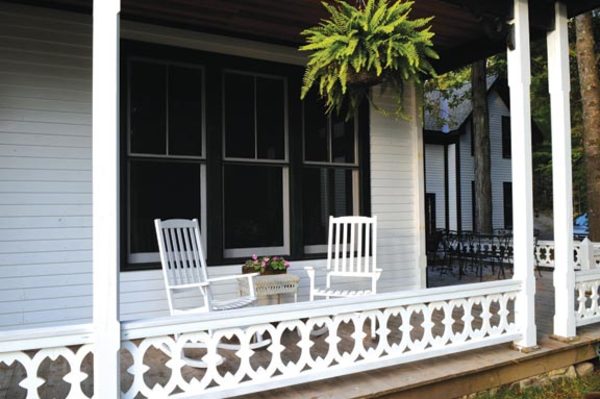
My wife, Trudie, and I have owned an 1880 Folk Victorian summer house on the shores of Lake George, New York, since 1986. Over two decades, we’ve undertaken dozens of repair and maintenance projects to arrest the home’s slide toward collapse.
After we moved in full time in 2002, we stepped up work considerably. Our most recent job was a wholesale replacement of the large, elaborately balustraded 130-year-old wraparound porch, which was so deteriorated that replacement was the only real option. I put my engineering background to work to try to improve the structural design and to stem future water damage. I decided to re-create the ornate scroll-cut wood balustrade using a (hopefully) weather-resistant expanded PVC trim.
Original Conundrum
Duplicating the porch rail’s intricate gingerbread balustrade was a challenge. The original 1880s railing consisted of many separate parts: a top and bottom rail, each measuring 2″ x 3″ with slots to secure individual baluster pieces; individual baluster sections cut in the shape of a narrow, stylized X, so that O’s formed where two pieces met; and separate wood filler pieces fitted into the X’s open top and bottom. The filler piece was intended to keep water out of the lower slot—but over 130 years, the paint had deteriorated and water had seeped into the bottom slot, causing the lower rail to rot.
Jim’s new baluster sections (at right and middle) are slightly longer than the originals—a design tweak intended to stave off water damage—but otherwise an exact match.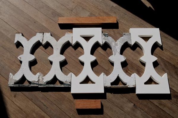
I decided to tweak the structural design in an effort to solve the problem of water entrapment in the lower rail, so I extended the balusters and sandwiched them between two separate top and bottom rails, eliminating the filler piece and water-trapping slot. Because the balusters had originally been cut by hand, and many also had warped or shrunk over the years, determining the original dimensions took some trial and error. I started by tracing the outline of several balusters onto vellum, but found there was no consistent shape. I tried to think how the original craftsmen might have created the shapes, and assumed they would have used simple radii with symmetrical placement. I drew several versions onto vellum and compared these to multiple original pieces, finally deciding that the design probably involved simple 4″ radius arcs for all of the shapes. When I drew this up full size, it looked like a reasonable reproduction of the originals.
Material Decisions
Once I had finalized the design, I asked several companies for quotes on cutting the balusters for me using a waterjet cutter or a similar method. One company suggested using a production router, but the cost was prohibitive for a do-it-yourself budget—about $20 for each of the 350 pieces (or close to $7,000). That got me thinking that maybe I could make a simple plywood template and cut them from pine using my own 2-hp plunger router. I got some 1/4″ down spiral router bits and tried some cuts on wood scraps. It took multiple passes to get the cut depth, and standard 3/4″ or 11/16″ wood didn’t match the existing balustrade thickness very well. I experimented with various composition trim boards, but they were heavy and didn’t cut well with the router, and I was afraid the resins wouldn’t survive the sun and dampness. I needed a better material, one that would be resistant to rot and warping, and one I could machine easily. I finally found it in expanded PVC trim boards, available through several local building stores.
I purchased a sample 20-foot length to see how well the material would cut with my router. I had to buy a 1×10 nominal size (9 1/4″ actual width) in order to yield the full 8″ width. The first step was to cut accurate 8″ x 18″ blanks (the basic baluster shape). The width was critical because 14 pieces would just meet the 112″ post spacing. The material cut easily with normal carbide saw blades using both a table saw and a radial arm saw. I used stops to cut 14 blanks from the 20′ length, which helped minimize waste. The smaller pieces were easier to control on the table saw, where I cut away one side first, and then the second at exactly 8″ so both sides would have the same cut edge (the as-manufactured edges were slightly cupped). These went back to the radial arm saw, where I used a production stop to get the exact length needed for each piece—precision was key to making the scroll templates work. Because there were a lot of cuts to be made, I spread the job out over several days.
A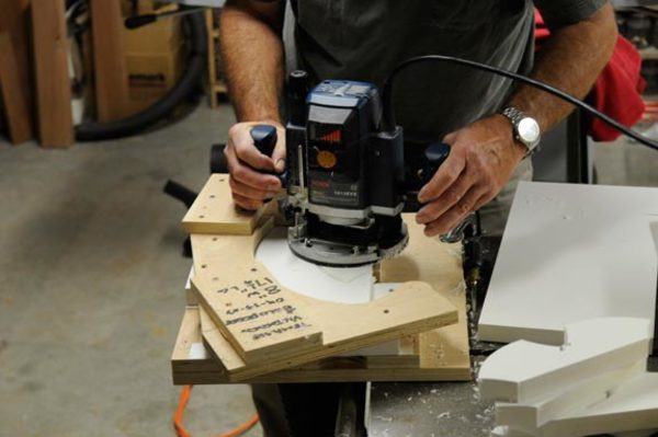
To cut the balusters, I created a couple of simple templates. The first, for the main pattern [A], was designed to cut one quadrant of the baluster’s side and consisted of 3/4″ cabinet plywood with a shape that would guide around the outside of the router base plate. Each baluster was positioned in the template and securely clamped (so pieces couldn’t slip and ruin the finished shape). The second template [B] was designed to cut the triangular window inside the upper and lower portions of each section.
B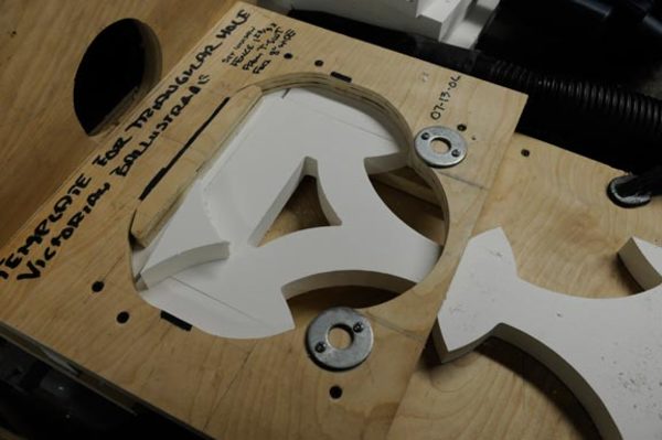
To get accurate radii, I used a homemade radius bar to guide the router for the larger one, then fastened a 2″ steel washer to the wood for the smaller radius. I used a reciprocating spindle sander to make the wood conform to the steel washer. I secured the separate pieces of the template with drive screws.
I experimented with various cutting depths to see how well I could do with two or three cuts, but found that I could cut the entire 7/8″ thickness in a single pass. This was important, as there would be more than 2,000 separate cutting operations, and doubling or tripling that would have added significant time. There was minor chatter (roughness) in the cuts from time to time, but that gave the edge a look similar to the band saw cut on the original balusters.
Chips were a problem, as the router produces a fluffy, bulky waste. I set up my shop dust collector beneath the template for the four outside cuts with the downward spiral bit, using part of a standard blast gate as a hose connection. This was quite effective and produced very little fugitive dust. In addition, the air the dust collector passed around the cutting bit and through the cut slot helped take the chips out of the cut and cool the material and bit.
For the window cut—a triangular opening at the top and bottom of each baluster—I needed an up-feeding bit (the down spiral wouldn’t allow the initial plunge through the material). I used a dust hood near the cut, but it wasn’t entirely effective in capturing the chips. (It might have been better to drill a starter hole and use the downward spiral bit and vacuum system for these as well.)
Being an engineer, I’m always interested in how my time compares with the cost of paying someone else to do the job. In all of the operations combined, I expended only 8 to 10 minutes creating each baluster.
Rail Reflections
Next, I tackled the rails. In the original design, the slotted bottom rail was a water trap vulnerable to rot. My design would consist of two top and two bottom rails. The top was composed of two 1″ x 2″ rectangular pieces. The bottom had the same overall dimensions, as well as a 15-degree slope to shed water. The rail material needed to be strong, stiff, and rot resistant. Since I had replaced the porch deck the previous year, I had leftover mahogany tongue-and-groove deck boards measuring 5/4″ x 3 1/2″. I used my table saw and jointer to cut some trial pieces to the 2″ width, then assembled a couple of short sections to see how it worked and looked. When I compared the cost of the deck material to several other alternatives, it was the least expensive option.
C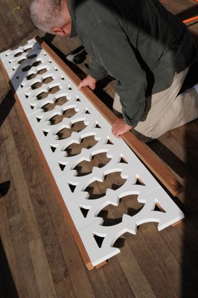
Assembly was simple. A top and bottom rail were placed on the floor, the balusters spaced along them, and the second rail set placed on top [C]. I squared the loose assembly, and drove 2 1/2″ galvanized trim nails into each corner. Next, I tapped the balusters into vertical alignment and re-squared the assembly, then drove four nails into each baluster on opposite corners. Once I got the hang of it, it only took me 25 minutes to assemble a full-length section.
D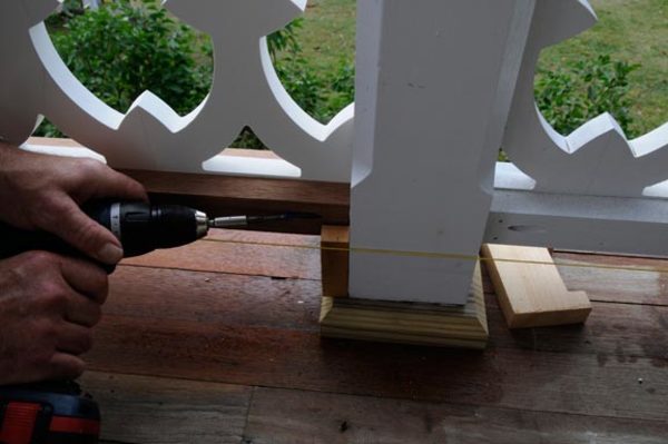
I chose pocket screws to fasten the railing sections to the post, putting holes to place them in the top and bottom rails after I cut the rails to length in my shop [D]. I made a spacer to position the pocket screw jig at exactly the same distance from the end of each rail. (My jig, from Kreg, comes with a special drill that produces the recess and pilot holes in one easy operation). After the rails were installed on the porch, I added additional pocket screws at the top inner rail to provide some extra strength for lateral loads. I figured each screw should be able to support 200 to 300 pounds in shear, so three screws atop each section gives an initial capacity of 600 to 900 pounds laterally at the ends, while the 10 screws in each 112″ section could support 2,000 to 3,000 pounds vertically. We’re still careful to limit the number of people sitting on the rail.
For the top rail, we chose to use a 5/4″ x 4″ mahogany square-edge deck board. While these don’t have the 15-degree water-shedding angle of the original rails, you can sit a wine glass or beer bottle on top—a useful feature.
After the sections were installed, I primed the wood and filled the nail holes using wood filler, and the pocket screw holes with plugs made specifically for my jig. I also painted a base coat of soft gloss white on both the PVC and the mahogany. While we’re still debating whether we want to paint the rails green, like the originals, we definitely enjoy having the balustrade up. The accent color can wait.