The Third Dimension From a practical standpoint, adding trim moulding means transitioning surfaces from two dimensions to three, all in the context of rooms where nothing is perfectly square or flush. Consider that repairing or replacing a length of 5″ cove moulding set at an angle (sprung) requires working with a special ruler before it’s placed on the wall below the ceiling. Then consider that cornices are traditionally built up from two, three, or more mouldings—complex compositions that can be difficult to replicate today. It all adds up to a process that’s as much about geometry and problem solving as it is about carpentry.
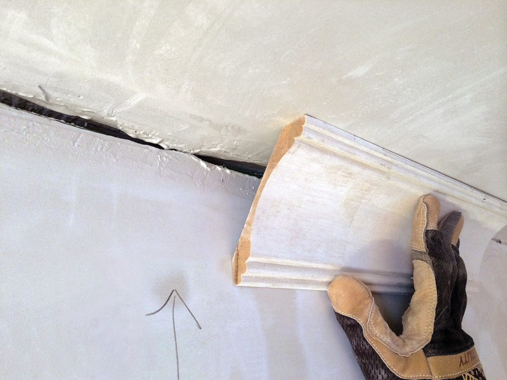
Positioning a “sprung” or angled crown moulding in a room that’s lost the original looks simple, but getting a professional result requires skill (as well as trial and error). Alex & Wendy Santantonio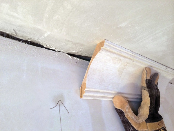
Just finding replacement material is a challenge when the irreplaceable has gone missing. The baseboards in a house built in 1900 were probably cut from true 1″ x 6″ stock. Today, that 1×6 board actually measures ¾” x 5 ½”. A cornice loaded with multiple coves, bevels, and ogee shapes may have been milled from a single piece of lumber. Or it might be composed of multiple mouldings built up to form the profile, meaning you must find all the composite parts at the correct size and scale—and then install them in the correct order!
A door surround with an elaborate cornice frames the view into a Georgian dining room defined by its mouldings. Carolyn Bates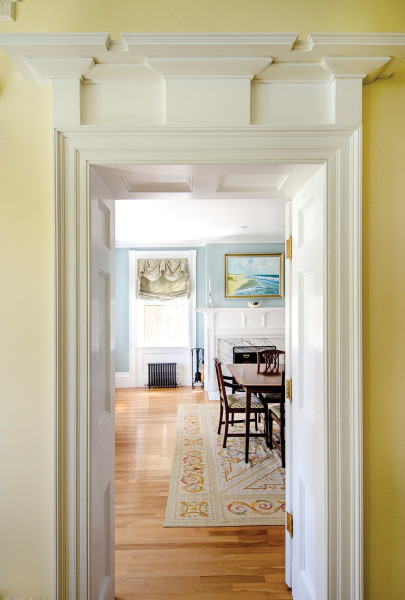
Pro Tip: Composite mouldings typically have underpinnings known as grounds—wood blocks, thin cleats, and the like that support the decorative relief structure with less weight.
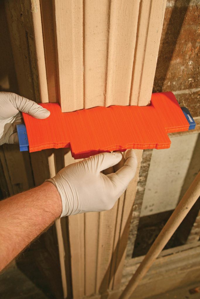
Finding a match invariably means having a facsimile of the profile on hand as you search. An easy trick to capture the missing profile is to copy it using a contour gauge. Then check out-of-the-way locations in the house for matching millwork. Look inside closets, on the stairs to the attic, behind radiators, or where a section of wall will be demolished for a new passageway. You may find just enough trim to make your repair.
An elaborate cornice from Driwood Mouldings, shown in corner profile, is composed of many elements. While some are wholly decorative, flat or square ground pieces help convey the illusion of massing. 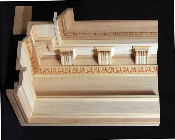
Or you can try matching the moulding with new stock. Search building-supply stores for trim that exactly matches the old in size, depth, profile, and wood species. For more complex mouldings, look to specialists that stock hundreds of historic profiles.
Still no luck? Try composing the moulding by building it up from common profiles. Even elaborate mouldings are generally a combination of shapes that appear on simple trim.
If the moulding is fairly straightforward (a one- or two-piece composition, say) and you have some basic carpentry skills, try making the replacement yourself.
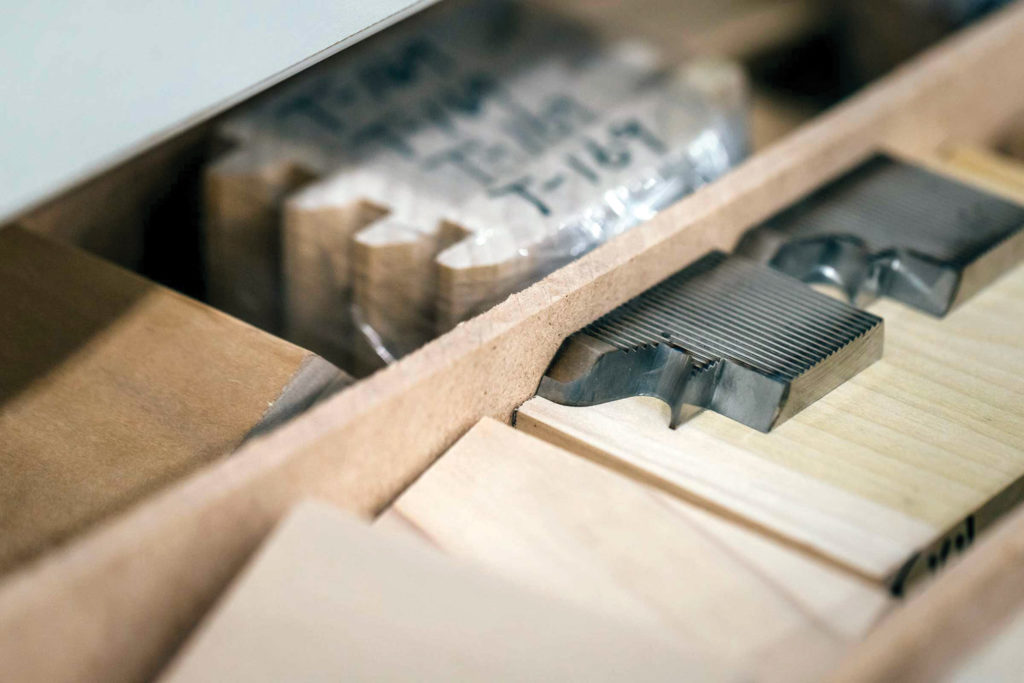
Commissioning bespoke millwork can mean ordering a custom knife like this one from Schere Brothers, to the tune of hundreds of dollars—well worth it for a good-size run. Courtesy Schere Bros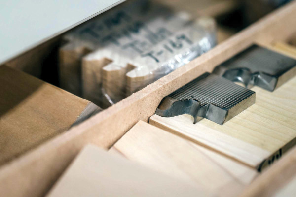
If the moulding is too complex to re-create any other way, you can ask a millwork specialist to make an exact profile of the moulding, create a knife for it, and run new stock. This only makes sense if quite a bit of the trimwork is missing or damaged, because the knife alone for a large moulding can cost $500 or more. Running costs are four or five times the cost of quality stock mouldings (i.e., $5 to $15 per linear foot).
A better option may be cobbling together a mix of stock and custom mouldings. One OHJ reader re-created a complex,
8″ tall cornice using six separate mouldings. Three were stock, two were custom components cut for a previous customer at the lumberyard, and the sixth was a stud cut to size as a ground piece. It was a perfect match for the unusual crown in the parlor.
Moulding Know-how
When finishing up newly installed mouldings, fill in nail holes with wood putty, then sand smooth. To minimize the number of nail holes, first mark all the studs in the room. Alex & Wendy Santantonio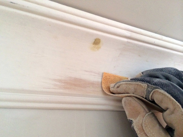
Use a pneumatic nailer, instead of a hammer and nails, to fasten trim moulding. It’s gentler on plaster.
Struggling with the coping saw? Reverse the blade to get a cleaner cut.
Each time a moulding is painted, paint fills the joints between the individual pieces of wood that compose it. The more layers of paint, the larger the joints become. The best solution is an obvious one: remove the moulding, clean it of excess paint on
the backside, and reinstall it.
Cutting Corners
“Turning the corner” is easily the most challenging part of any moulding installation or repair. It helps if you aced geometry in high school. For all others, learn to use a miter box, preferably one with a clamp. More experienced? Upgrade to a compound miter saw.
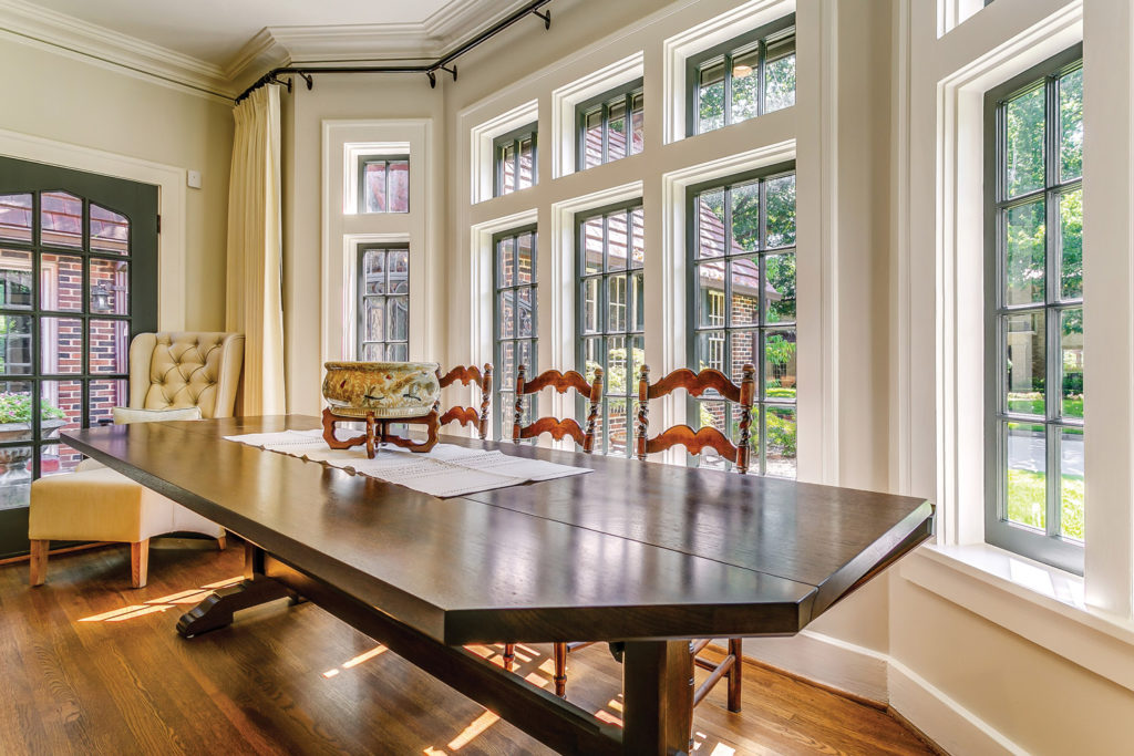
A layered cornice and deep window casings add depth and classical proportion to a projecting bay with multiple windows and mullions. Courtesy Hull Millwork
A miter box is a three-sided wood or plastic tool with open ends, which allow pieces of moulding or millwork to slide into position. It’s used with a backsaw, a rectangular saw with a reinforced spine that keeps the blade rigid. The saw fits into vertical slots in the miter box, set at the precise 45 or 90 degree angles needed to cut miter joints. You’ll need to cut a host of them if your job includes areas where the moulding turns at an outside corner.
To miter trim at an outside corner, cut two pieces of moulding at mating 45-degree angles. Fit together to form a tight right angle. It’s OK if there’s a slight gap at the back of the joint; it’s the “show” side that’s important. For mouldings to be installed flush (resting on the surface of the wall), nail the two mitered sides together with small finishing nails. If the moulding is sprung (installed at an angle to span perpendicular surfaces), glue the joint together.
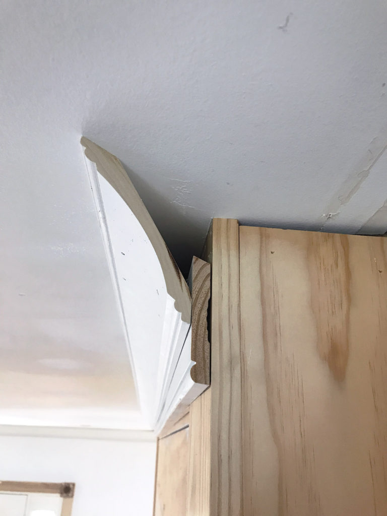
At inside corners, use a coped joint for a better fit. (Well-fitted miter joints and coped joints end up looking the same.) In woodworking, coping refers to removing the bevel from a mitered piece of moulding: actually cutting the negative shape of the profile on a piece of trim. The traditional method is to cut away extra material with a coping saw, a D-shaped metal-frame saw with a thin blade held under tension. To make the first part of a coped joint, cut a 90- degree end on one piece of moulding and butt it into the corner. Miter the second piece of trim at 45 degrees for an inside miter. Then use the coping saw to remove excess material on the back of the mitered moulding.
To make the cut, first shade the leading edge of the moulding profile with a pencil. Hold the moulding at the correct angle (how it will fit against the wall), then tilt back slightly. Saw through the wood along the leading edge at 90 degrees, following the penciled line. Since the leading edge is set at an angle, the thin, narrow blade cuts away enough material behind it so that the moulding can fit against (and slightly on top of) the mating moulding. Test the coped moulding against the piece already in place. Get a perfect fit by smoothing any rough edges along the coped cut with a wood file and sandpaper.
Alternatively, scribe the profile of the first moulding onto the second one, using a compass fitted with a pencil. Set the compass to the width of the lumber. Butt the boards at a right angle, and draw along the joint to scribe the profile on the second piece. Use a coping saw to cut along the line. Now it should fit tightly against the first board.
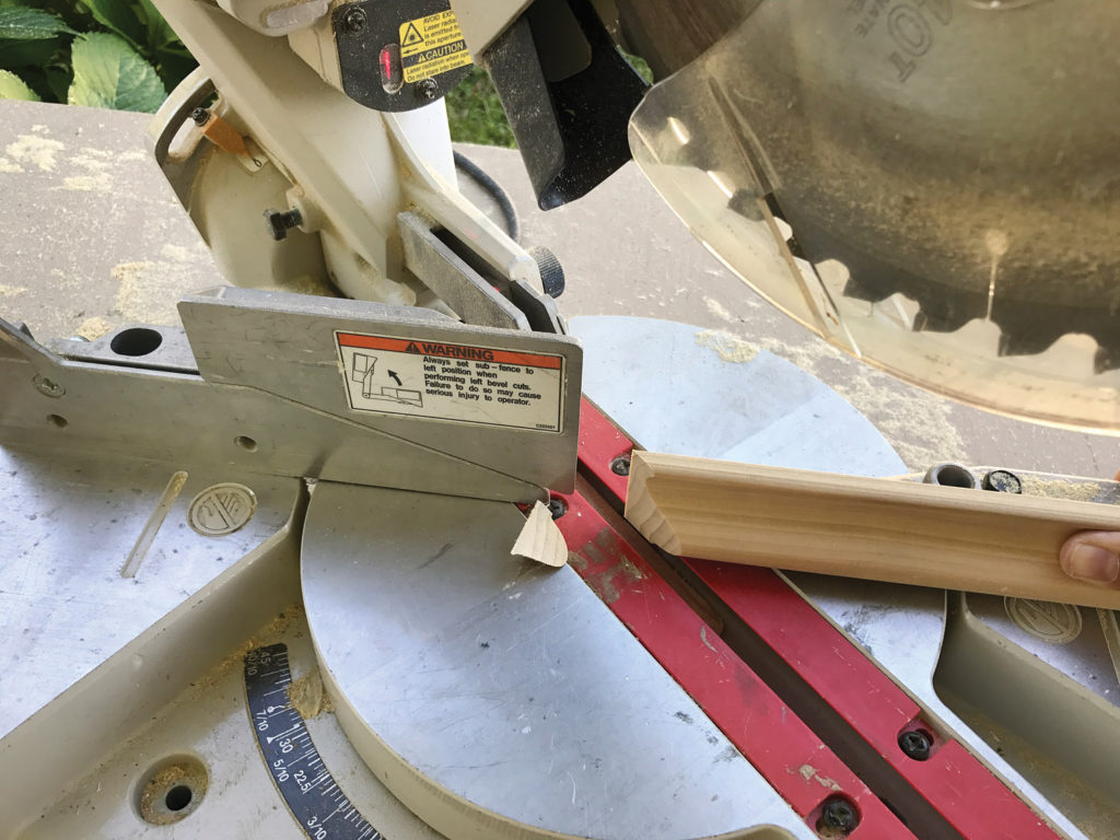
Prefer power tools to hand saws? Cut a small scrap piece of moulding in the correct profile and use it to make a tracing on the second piece of moulding. Then cut away the excess material from the back with a jigsaw.
Coping With a Jigsaw
If you’re not comfortable working with a coping saw or you don’t have one, you can use this shortcut for coped joints, using a scrap piece of moulding and a jigsaw.


Match for a Patch
Need to copy the profile of a moulding so that you can match it at the lumberyard, or re-create it in the workshop? Try a contour gauge. Sometimes called a profile comb or moulding profiler, a contour gauge is a row of steel or plastic pins, held parallel and tightly packed together inside a housing. The gauge permits each pin to move independently within the same plane. When pressed against a moulding, the pins take an impression of the surface, outlining the general profile. When shopping for a match for existing mouldings, take the tool with you to the store.
Restoration specialist Bill Rainford uses a contour gauge to capture the profile of a moulding. 
For best results, hold the gauge perpendicular to a section of undamaged moulding that’s free of excess paint. Gently push the needles in by hand to capture every contour. Lock the gauge and lay it on a piece of paper to trace. To make a patch, trace the profile on both ends of a piece of suitably sized stock lumber, which then can be planed, carved, or otherwise shaped to replicate the original moulding. Consider the profile gauge a starting point. Once the patch is in place, sand or file it to remove variations between the new and old moulding. Fill any gaps with caulk.
Essential millwork terms
- Base Moulding Also called a baseboard, skirting board, or mopboard, a board that covers the joint between the wall and the floor; it’s usually topped with a base cap.
- Coped Joint A joint between two mouldings where one board is cut to match the profile of the other.
- Cornice The upper part of the entablature, from which crown moulding is derived.
- Corner Block A trim piece used on the upper corners of windows and doors, common in Queen Anne architecture. A bull’s-eye or rosette is often set in the block.
- Crown A projecting ornamental moulding or assemblage of mouldings along the top of an interior wall.
- Flush Moulding that rests directly on the wall or ceiling
- Ground Wood blocks, cleats, or hollow boxes used to support larger mouldings. Some grounds are exposed as part of the moulding; some are not.
- Miter Joint A joint between two members cut at an angle to each other, where each is cut at an angle equal to half the angle of the junction (usually a right angle).
- Profile The relief section of a moulding, which can be convex, concave, or decorated with ornament.
- Sprung Moulding that is installed on-angle with a void behind it, with one edge on the wall and one on the ceiling.
Two-part Crown
By Alex Santantonio
When Wendy and I began a project to install two-part crown moulding in the dining room of our 1910 Foursquare, we knew to expect wavy plaster walls and an inconsistent ceiling height. To help us identify problem areas and create consistent install lines, we created two templates, or jigs. Then we hit on the idea of creating a level line using a laser.
While adding the backer board added more depth to the crown, it meant taking extra care with the installation line. 
The first jig was a mockup of the two-part crown itself: a large piece of cove moulding mounted on a flat piece of backer board with a beaded edge. Only the bottom inch or so of the backer would show beneath the cove moulding.
Since we intended to install the backer boards first, followed by the cove moulding, we needed a marker to set the reveal. I cut a representation of the reveal that allowed us to set a pencil line where the bottom of the backer board should fall, keeping it more or less level around the room. This allowed us to force the crown up or down as we went, for a consistent exposure.
To keep everything level, we used a laser line that showed where the bottom of the backer should sit—essential, since the ceiling and walls are wavy, not square and plumb. Mounting the laser was surprisingly easy: I screwed a piece of metal from leftover ductwork to the beam, then used magnets from the laser level housing to position it as needed. The laser line let us see where we needed to fudge the backer up or down, in an attempt to split the difference where the ceiling was too out of whack.
When we began the install—working around the room clockwise—we discovered that it made more sense to install sections of backer and crown, working only one or two sections ahead, rather than installing all the backer at once, followed by all the crown. We also learned to not fully nail down the backer until finishing up the previous crown. This let us test-fit the next crown.
To measure long runs, we used a small 30′ pocket laser distance measurer to get our cut lengths. It’s more accurate and much easier than a tape measure, especially for lengths of 10′ or more.
One mistake we didn’t make this time was installing the crown all around the room without leaving space for the final backer board at our return to the starting point. Without proper spacing, we’d need to cope the final backer piece into the first piece of crown—awkward to say the least. To leave room, I held a loose piece of backer perpendicular to the first backer board and gave myself a pencil line to indicate where the crown should start. The last backer board slid into place behind the first crown.